

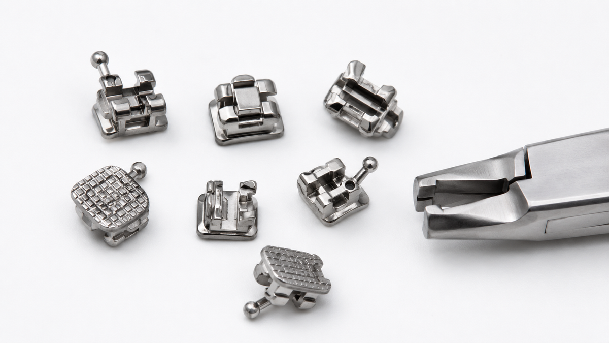
Metal powder pressing turns loose metal powder into a solid part in one stroke. Powder fills a die, a punch comes down, and out comes a green compact shaped like the finished component. No melting, no chips, and material utilization above 97%.
That is why press-and-sinter shops still ship millions of gears, bushings, and brackets a year. It is also why engineers searching for a manufacturing route often stop at metal powder pressing without checking whether the part in front of them can be pressed at all. Sometimes it cannot.
This article covers how compaction works, how to size a press, the design rules that decide pressability, the defects that show up on the floor, and the point where the process runs out and MIM takes over. XY-GLOBAL has quoted both routes since 2010.
What is metal powder pressing?
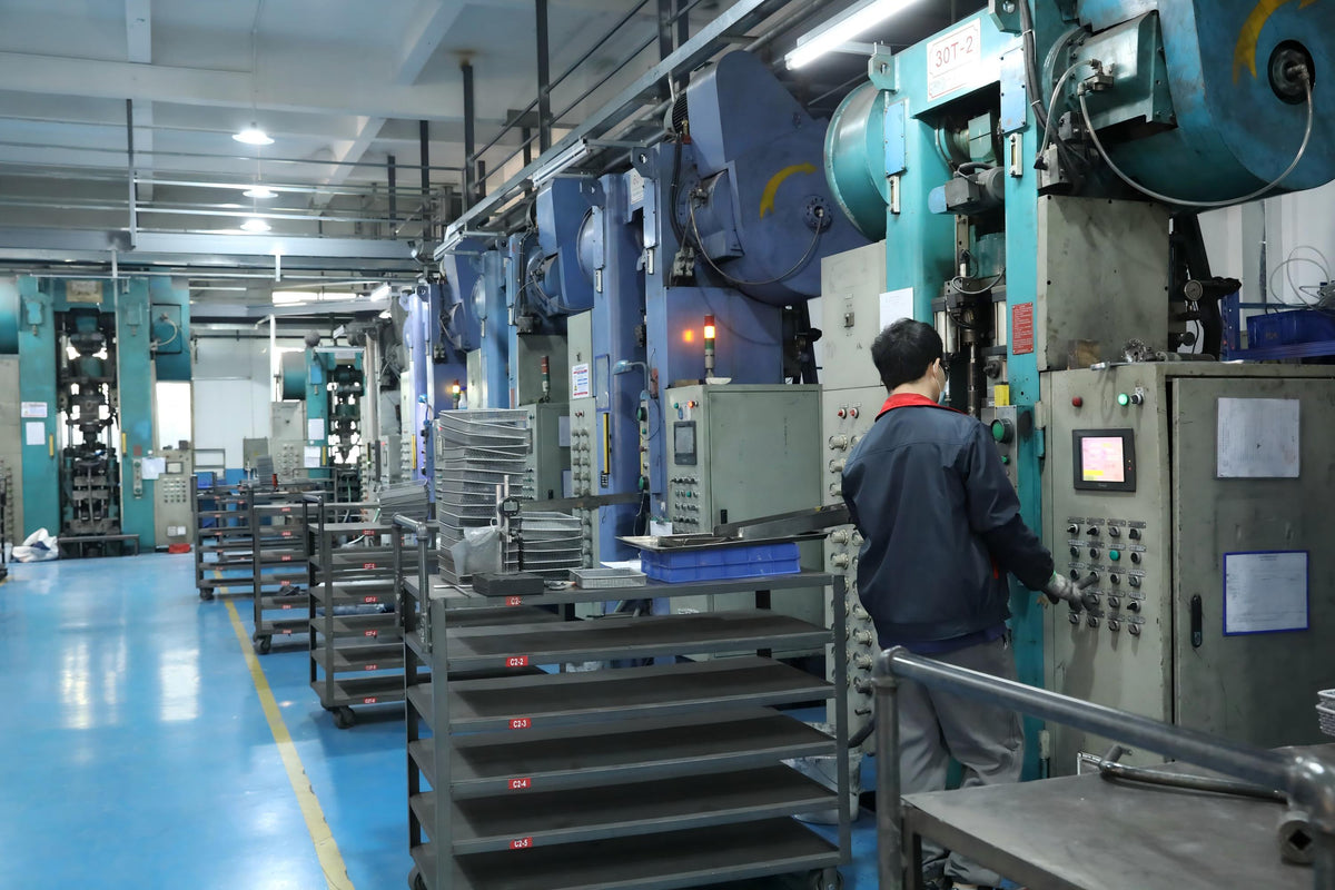
Metal powder pressing is a powder metallurgy forming process. Metal powder is compacted inside a rigid die under uniaxial pressure at room temperature, producing a green compact: a part with the intended geometry but only partial density and strength. The compact then goes to a sintering furnace, where the particles bond.
Forming is cold. Pressure runs 400–800 MPa (58,000–116,000 psi), and heat enters only at sintering. Before that, a compact sits at roughly 85–92% of theoretical density.
Shape comes from a hardened steel cavity and matching punches, so the part has to eject along the pressing axis. Nearly every design rule below follows from that one constraint.
Because the part is formed to size, there is no gate, no runner, and no machining allowance beyond what finishing needs. Material utilization is usually above 97%.
The terms metal powder pressing, powder compaction, and die compaction mean the same thing. Press and sinter refers to the same route including the furnace step.

The process, step by step
1. Powder preparation and die filling
Powder is blended with a lubricant, usually 0.5–1% zinc stearate or an amide wax, to cut die-wall friction and allow clean ejection. A feed shoe meters the blend into the cavity.
Fill control sets dimensional capability. A press is a volume machine, not a force machine, so the mass of powder in the cavity sets the height of the compact. Most production presses control fill by cavity volume. Tighter work uses weight-fill or per-punch die-wall adjustment.
Powders for pressing are coarse, usually 45–150 µm, because they have to flow and fill a cavity in a fraction of a second. That coarseness caps feature detail. It is the first technical reason MIM exists.
2. Compaction
The upper punch descends and pressure builds. In a single-action press only the top punch moves. In a double-action or floating-die setup both sides load the compact, so density distributes more evenly through the part height.
Typical compaction pressure by material:
|
Material |
Typical compaction pressure |
|
Pure copper, brass |
200–400 MPa |
|
Iron and low-alloy steel |
400–600 MPa |
|
Stainless steel (316L, 304L) |
600–800 MPa |
|
Tool steel, high-alloy |
700–1,000 MPa |
Above roughly 600 MPa, each extra unit of pressure buys less density. That is why shops chasing higher density move to warm compaction or double-press-double-sinter instead of buying a bigger press.
3. Ejection
The lower punch or ejector pins push the compact out of the die. Ejection is the most defect-prone second of the cycle. Springback leaves the part slightly larger than the cavity, so it drags against the die wall on the way out.
Shop-floor numbers that matter: ejection speed 0.1–1 mm/s, die-wall taper 0.1–0.3°, and a dwell of 2–10 seconds before ejection so elastic strain can relax.

4. Sintering
Green compacts sinter at 1,120–1,300 °C in endogas, nitrogen-hydrogen, or vacuum, for 20–60 minutes at temperature. Particles diffusion-bond, porosity rounds and shrinks, and strength climbs from a few MPa to the range of wrought metal.
Dimensions move here too. Pressing dies are cut oversize to compensate for sintering shrinkage, typically 0.5–2% linear for iron-based materials. MIM shrinks far more.
What happens inside the die
Compaction runs through three mechanisms in sequence, and each one leaves a mark on the part.
At low pressure, particles slide and rotate into tighter packing. Voids shrink, but the particles keep their shape. This stage buys density cheaply.
As pressure climbs, contact points yield and flatten. Contact area grows, cold welds form, and the compact develops green strength. Without this stage the part would crumble on ejection.
Near peak pressure, most of the additional strain is elastic. When the load releases, the compact rebounds by 0.1–0.3% and stored stress redistributes.
Springback causes two chronic problems. Dimensions drift, so the die has to be cut to compensate. And residual stress turns into lamination cracks when ejection is too fast or lubrication too lean.
Then there is the density gradient, which you cannot design away. Friction between powder and die wall makes pressure decay with distance from the punch. In a single-action press the top of the part is denser than the bottom. A part with a 3:1 height-to-diameter ratio can show 0.3 g/cm³ of variation top to bottom. That gradient becomes differential shrinkage in the furnace, which is how a part that measured straight off the press comes out of sintering bowed.
Double-action pressing and floating dies hold the variation under about 5%. Any part with a height-to-diameter ratio above roughly 2:1 should be quoted that way from the start.
Pressing routes
|
Route |
How it works |
Pressure |
Best for |
Limitation |
|
Single-action uniaxial |
Top punch only |
400–800 MPa |
Bushings, washers, thin plates |
Strong density gradient; H/D ≤ ~2 |
|
Double-action / floating die |
Both punches load the compact |
400–800 MPa |
Multi-level parts, longer cores |
Tooling cost rises with levels |
|
Cold isostatic pressing (CIP) |
Fluid pressure on a flexible mold |
100–400 MPa |
Large, complex, or very tall shapes |
Slow cycle; needs machining to final form |
|
Hot isostatic pressing (HIP) |
Gas pressure at temperature |
100–200 MPa at 800–1,350 °C |
Fully dense critical parts, defect healing |
Expensive; usually a post-step |
|
Warm compaction |
Powder and die heated to 120–145 °C |
600–800 MPa |
Higher green density (+0.1–0.2 g/cm³) |
Needs dedicated lubricant and heated tooling |
|
Double-press-double-sinter |
Press, sinter, re-press, re-sinter |
600–1,000 MPa |
Gears, connecting rods, high-load parts |
Two furnace cycles; cost per part climbs |
For most custom component programs the real choice is between double-action die pressing and MIM. CIP and HIP cover large parts and density levels that die pressing cannot reach.
Sizing a press
Required tonnage is pressure times projected area, plus a margin.
Tonnage (tonnes) ≈ P (MPa) × A (cm²) ÷ 98
A 316L flange with 50 cm² of projected area at 700 MPa needs 700 × 50 ÷ 98 ≈ 357 tonnes. A 400-tonne press handles it. A 250-tonne press does not, whatever you do to the cycle.
Two practical consequences. Projected area sets the machine, not part weight, so a thin wide part can need a bigger press than a heavy compact one. And when a quote comes back with an odd press assignment, projected area is usually the reason.
Design rules for powder pressing
These decide pressability before any commercial discussion starts.
- Eject along one axis. No undercuts, no cross-holes, no internal threads, no radial grooves. Anything that would trap the part in the die gets added later by machining.
- Minimum wall 1.5–2 mm. Thinner walls fill poorly and eject fragile. Below 2 mm, expect density loss at the wall and a real scrap penalty.
- Height-to-diameter ratio ≤ 2:1 single-action, ≤ 3:1 double-action. Past that, density gradient dominates everything else.
- Limit the levels. Every change in part height along the pressing direction needs its own punch. Four levels is routine. Eight is a tooling project.
- Draft is not required, but relief helps. Pressed parts eject straight, so vertical walls are fine. A small taper or relief at the ejection end reduces die-wall scoring.
- Round internal corners to R 0.2 mm minimum. Sharp inside corners become low-density zones that crack on ejection.
- Avoid thin, tall standing walls and unsupported bosses. They fill unevenly and shear during ejection.
- Design for the tooling, not the drawing. A 0.05 mm step is trivial to machine and can double die cost, because it needs another punch level.
If a design fails three or more of these, it is not a pressing part. Say so early, before someone pays for a die they cannot use.
Common defects and their causes
|
Defect |
What it looks like |
Cause |
Fix |
|
Density gradient |
Uneven hardness, distortion after sintering |
Die-wall friction, single-action pressing |
Double-action or floating die; better lubricant |
|
Lamination |
Horizontal cracks across the pressing axis |
Excessive springback, short dwell, over-pressure |
Lower pressure, longer dwell, adjust lubricant |
|
Ejection cracks |
Vertical splits near the die wall |
Ejection too fast, scored die, no taper |
Slow ejection to 0.1–1 mm/s; polish die; add taper |
|
Edge chipping |
Broken corners and rims |
Low corner density, loose die clearance |
Larger corner radii, tighter clearance |
|
Springback oversize |
Part consistently large, out of tolerance |
Pressure too high, poorly compressible powder |
Lower pressure, more compressible grade |
|
Weight scatter |
Height varies part to part |
Low flowability, bridging in the feed shoe |
Coarser or spherical powder; more lubricant; adjust fill |
|
Sintering distortion |
Bowed or oval parts |
Density gradient carried into the furnace |
Fix compaction uniformity, not the furnace |
Diagnose in that order: fill, compaction uniformity, ejection, sintering. Most sintering problems arrive at the furnace already bowed.
Where die pressing stops working
Metal powder pressing is efficient inside its envelope and useless outside it. Five limits account for nearly every part that leaves for MIM.
- Complexity in the third dimension. A cross-hole, side slot, undercut, or thread cannot be ejected from a rigid die. It gets machined afterward, which eats the cost advantage.
- Thin walls and fine detail. Coarse powder cannot reproduce a 0.3 mm wall or a 0.2 mm rib. Detail below about 0.5 mm is out of reach.
- Small parts with tight tolerances. Fill scatter is worse and handling is awkward. The tolerance floor is hard to hold.
- Low and mid volume. A die set is a single-purpose investment. It pays back at high annual volume on a frozen design, and it punishes any change.
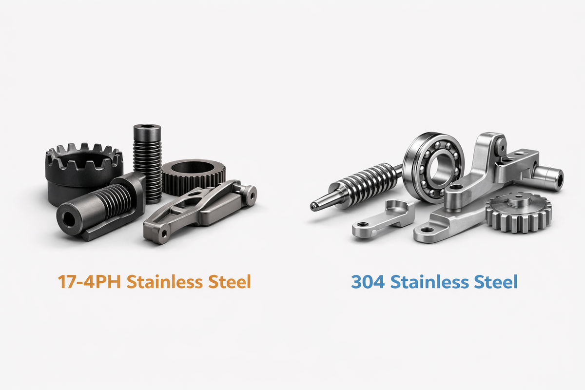
- High-alloy and reactive materials. Segregation and poor compressibility make 17-4PH, titanium, and tungsten-heavy compositions difficult to press consistently.
Point 4 gets underweighted. Die tooling is cheap for simple geometry and expensive for complex geometry. MIM tooling runs the other way, since a mold cavity has no punch stack. For a complex part at 10,000 pieces a year, MIM tooling often costs less than the multi-level die it replaces.
Metal powder pressing vs. MIM
MIM is the same powder metallurgy family with two substitutions: a mold instead of a die, and fine feedstock instead of coarse powder.
|
|
Metal powder pressing |
MIM |
|
Forming |
Rigid die, uniaxial punch, cold |
Steel mold, thermoplastic feedstock, injected |
|
Powder size |
45–150 µm |
8–20 µm (typically under 22 µm) |
|
Binder content |
0.5–1% lubricant |
35–50% by volume |
|
Geometry freedom |
2.5D; no undercuts or cross-holes |
3D; undercuts, cross-holes, threads, mixed wall sections |
|
Minimum wall |
1.5–2 mm |
0.3–0.5 mm, lower in micro MIM |
|
Green strength |
Handleable immediately |
Low; handled on trays until debinding |
|
Linear shrinkage |
0.5–2% |
15–20%, isotropic |
|
Typical tolerance |
±0.1 mm, tighter with sizing |
±0.3% of dimension; ±0.01 mm on small features |
|
Density |
85–92% green, 90–95% sintered |
96–99% of theoretical |
|
Part size |
Kilograms feasible |
Best under 50 g, practical limit ~100 g |
|
Tooling |
Die set; cost scales with punch levels |
Mold; cost roughly independent of complexity |
|
Economic volume |
High volume, simple geometry |
~5,000+ pcs/yr on complex parts, lower with multi-cavity |
|
Best-fit materials |
Iron, low-alloy steel, copper, brass, simple stainless |
17-4PH, 316L, titanium, tool steels, Kovar, specialty alloys; ceramics via CIM |
Neither column is better. They answer different drawings.

When MIM wins
- Cross-holes, undercuts, internal threads, or any side feature a die cannot eject
- Walls below 1.5 mm, or parts under 5 g with features below 0.5 mm
- Roughly 5,000 to several million pieces a year on a complex shape
- High-alloy stainless, titanium, or controlled-expansion alloys that press poorly
- Density that has to be functional: sealing surfaces, fatigue-loaded parts, polished optical mounts
When pressing still wins
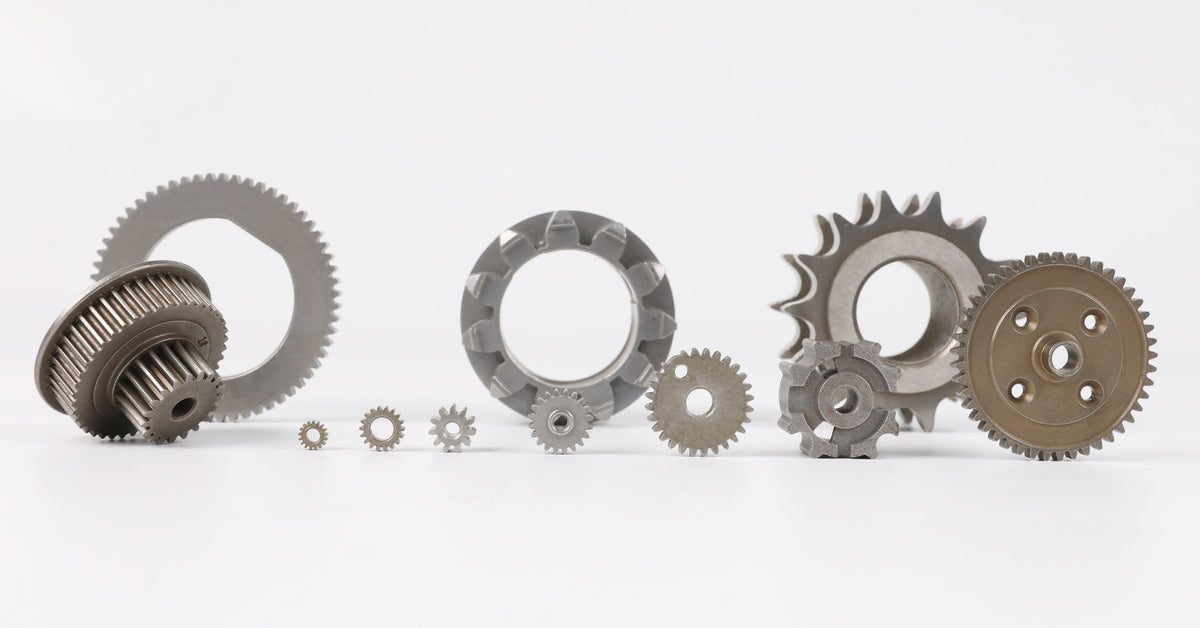
- Simple axial geometry at very high volume: gears, bushings, sprockets, counterweights
- Large or heavy parts, where MIM's size ceiling and binder burnout risk rule it out
- Structural parts where 90–93% density is enough and cost drives the decision
- A frozen design that will amortize tooling over years
We quote pressing-route parts to MIM inquiries fairly often. Running a bushing through a MIM line just makes the bushing more expensive.
Materials
Pressed: iron and iron-copper blends, low-alloy steels with copper, nickel, or molybdenum additions, 304L and 316L stainless, brass, bronze, nickel silver, aluminum, and tungsten carbide for cutting tools.
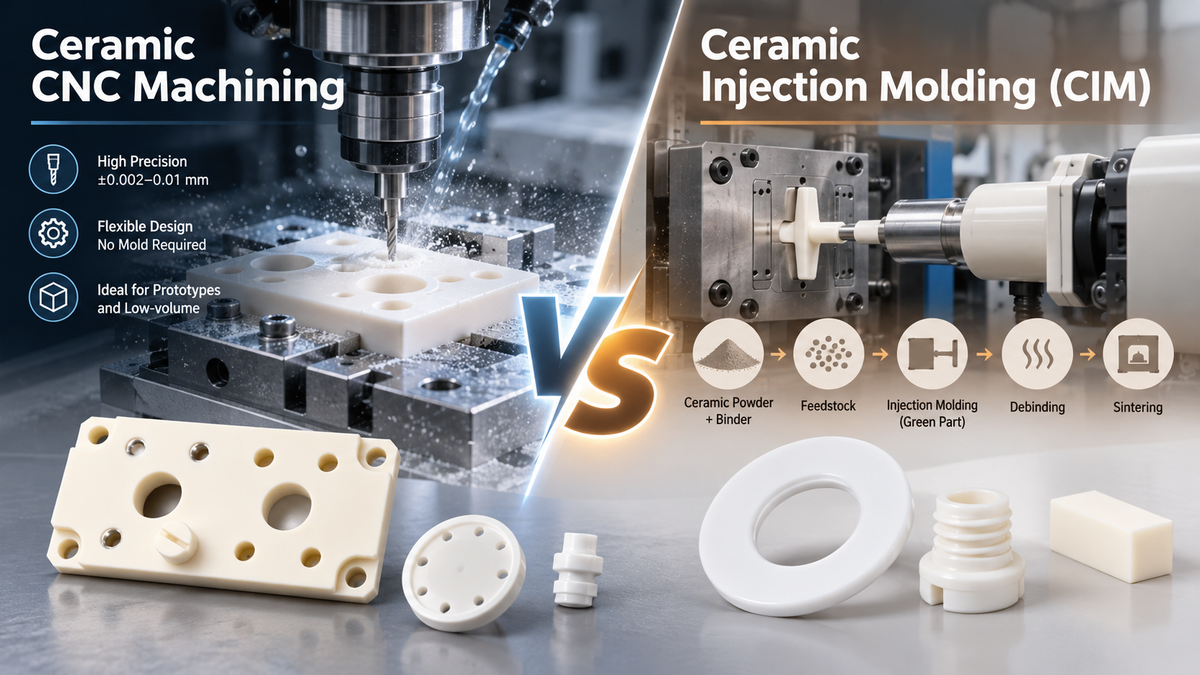
MIM: 17-4PH and 316L, 420 and 440C martensitic grades, 4140 and tool steels, iron-nickel soft magnetic alloys, Kovar and controlled-expansion alloys, titanium and titanium aluminide, tungsten-heavy alloys, plus alumina, zirconia, and aluminum nitride through ceramic injection molding.
The material callout often decides the route on its own. If the drawing says 17-4PH in the H900 condition with a 0.4 mm wall, the pressing discussion is over before it starts.
Where each process shows up
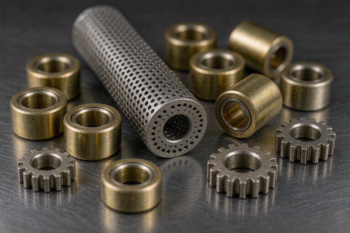
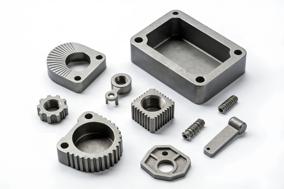
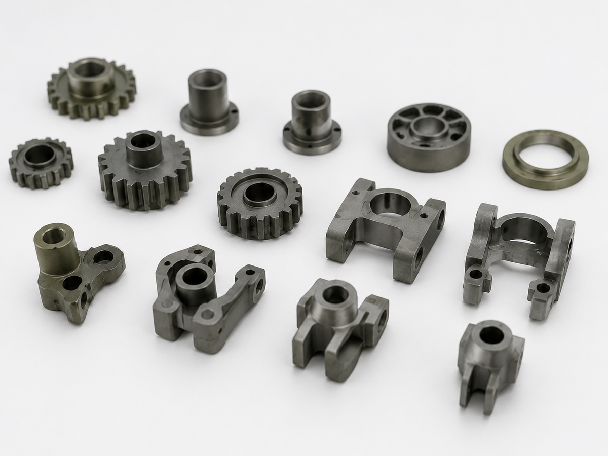
Press and sinter: transmission and engine components, oil-pump rotors, sintered gears, self-lubricating bushings, structural brackets, power-tool counterweights, lock hardware.
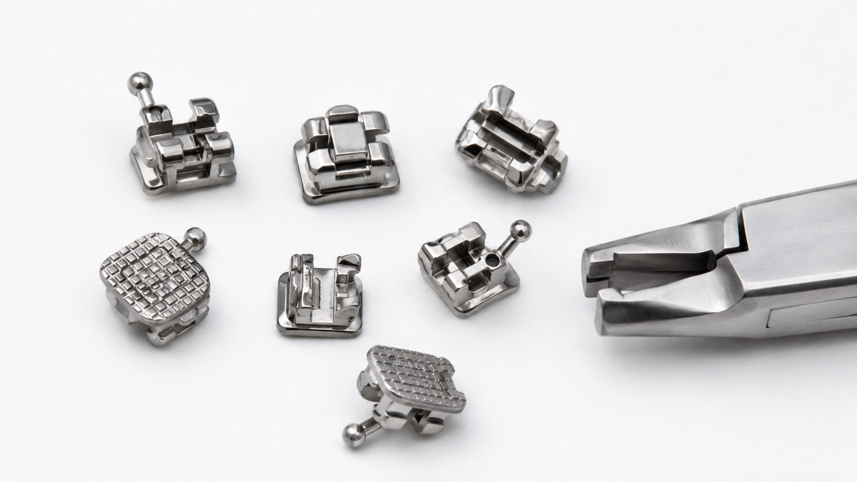
MIM: minimally invasive surgical jaws and shaft components, orthodontic brackets, endoscope housings, optical mounts, fiber-optic ferrules, semiconductor handling components, micro gears, sensor housings, fuze parts.
XY-GLOBAL runs MIM and CIM for three verticals: medical and dental, semiconductor, and optical. Where a program belongs on a press, we say so and quote it that way.
Six questions for a supplier
- Do they ask about projected area and annual volume before quoting? Press selection and MIM economics both turn on those two numbers.
- Will they send a DFM report before cutting tooling? XY-GLOBAL issues a DFM and mold-flow analysis before any mold is made, so density, gate, and shrinkage problems get found on paper.
- Can they show green-density or sintered-density data, not just a dimensional report? Density is what predicts whether the part performs.
- Which certifications cover the line the part actually runs on? ISO 9001 and ISO 13485 are the baseline for industrial and medical work.
- How do they handle first article and PPAP? A supplier who cannot describe the path has not run it at volume.
- Do they debind and sinter in-house? Outsourced furnacing is where dimensional control goes.
For calibration, our own numbers: a 5,000 m² plant in Shenzhen, 80 people with half of them engineers, 300+ projects and 20,000+ parts per month, ISO 9001:2015 and ISO 13485:2016, tolerances published down to 1 µm on micro features.
FAQ
Is metal powder pressing the same as MIM?
No, though they are close relatives. Both compact metal powder and both sinter the result. Pressing forms the shape in a rigid die from coarse powder. MIM injects a fine-powder feedstock into a mold, then removes the binder before sintering. Pressing handles axial geometry; MIM handles small parts with shapes pressing cannot make.
What pressure is used in metal powder pressing?
Most ferrous parts run 400–800 MPa (58,000–116,000 psi). Copper and brass run lower, 200–400 MPa. High-alloy and tool steels sit at the top of the range or above. Past roughly 600 MPa, each extra unit of pressure buys less density.
How large a part can be pressed?
Pressed parts can weigh several kilograms, limited by press tonnage and projected area. A 400-tonne press handles about 560 cm² at 700 MPa. MIM's ceiling is much lower, around 50–100 g in production.
Why do pressed parts have uneven density?
Die-wall friction makes pressure decay with distance from the punch, so the end nearest the punch is denser. Single-action pressing at a 3:1 height-to-diameter ratio can produce measurable top-to-bottom variation, which becomes differential shrinkage during sintering.
Can pressing make undercuts or cross-holes?
No. A rigid die requires the part to eject along one axis, so any trapped feature has to be machined afterward. This is the main reason complex parts move to MIM.
How tight a tolerance can pressing hold?
Usually ±0.1 mm as-sintered, tighter with a sizing or coining step. MIM holds ±0.3% of dimension, which on small medical and optical features works out to ±0.01 mm or better.
What this comes down to
Metal powder pressing is still the cheapest way to make a simple metal part in volume. MIM marketing does not change that. But the process has a hard boundary: one pressing axis, walls of 1.5 mm or more, coarse powder, and a die that only pays for itself on a frozen high-volume design.
If the drawing sits inside that boundary, press it. If it has a cross-hole, a 0.4 mm wall, 17-4PH, or a shape that only exists in three dimensions, MIM is the only route that works.
Send the drawing and the annual volume. We will tell you which route it is, and we will tell you before you spend money on tooling.
Condividi:
Cold Isostatic Pressing in Ceramics: Producing Uniform Ceramic Parts for Precision Applications
Powder Metallurgy vs Casting: How to Choose the Right Process