

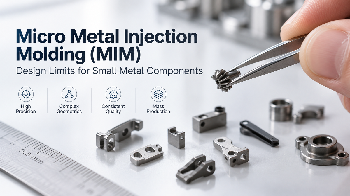
Metal injection molding(MIM) is well suited for producing small metal parts with complex geometry, especially when conventional manufacturing methods become inefficient or difficult to scale.
For very small components, however, the challenge is not simply making the part smaller. As dimensions decrease, powder size, feedstock flow, mold filling, debinding, sintering shrinkage, tooling accuracy, and inspection capability all become more critical.
This is where Micro MIM becomes different from standard metal injection molding.
A successful micro MIM project depends on understanding what features can be molded reliably, which dimensions need special control, and where the design should be adjusted before tooling.

What Is Micro MIM?
Micro MIM refers to metal injection molding used for very small and highly detailed metal components.
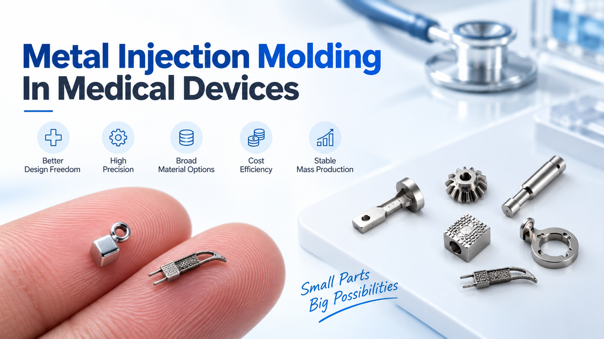
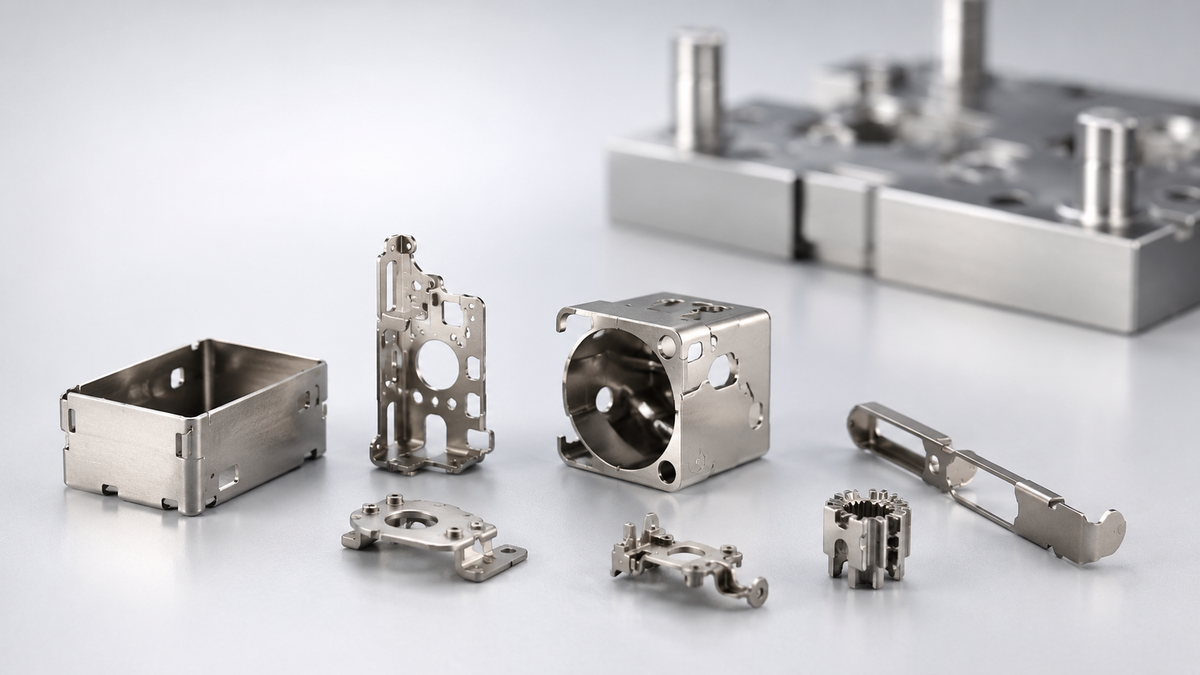
These parts are commonly found in medical devices, precision instruments, electronics, compact mechanisms, robotics, wearables, and miniature mechanical assemblies. Typical parts may include small structural components, micro gears, locking elements, miniature housings, connector parts, or other precision metal features that are difficult to produce economically with conventional processes.
There is no single universal size that defines micro MIM. In practice, the term usually applies when the part has very low weight, thin walls, small holes, narrow slots, fine ribs, or tight dimensional requirements. The difficulty increases when several of these features appear on the same part.
Micro MIM therefore should not be judged by part size alone. A small component with simple geometry may be relatively easy to produce, while another part of the same size with deep holes, thin walls, and asymmetric geometry may require much more engineering control.

Key Micro MIM Design Limits
Micro MIM can reproduce features that are difficult to manufacture efficiently by other processes, but every design still needs to respect practical manufacturing limits.
| Design Feature | Typical Consideration |
| Wall Thickness | Thin walls require stable mold filling |
| Small Holes | Limited by pin strength and powder flow |
| Deep Holes | Higher aspect ratios increase tooling risk |
| Ribs | Must fill completely without creating distortion |
| Slots | Narrow slots require careful gate and vent design |
| Sharp Corners | Radii are preferred where possible |
| Threads | Possible in some designs but require evaluation |
| Undercuts | Possible with special tooling |
| Flatness | Can be affected by sintering distortion |
| Tight Tolerances | Critical dimensions need additional process control |
These points should not be treated as fixed rules. Material, component geometry, mold design, production volume, and inspection method all influence what can be achieved reliably.
Minimum Wall Thickness In Micro MIM
Wall thickness is one of the first features that should be reviewed.
For many small components, a wall thickness around 0.3–0.5 mm may be practical depending on the material, flow length, and overall geometry. In specially optimized micro MIM applications, smaller features may be possible, but the complete structure must be evaluated rather than looking at one wall in isolation.
As the wall becomes thinner, mold filling becomes more difficult and the risk of incomplete filling, weld lines, uneven packing, and feedstock separation increases. Thin sections are also more sensitive during debinding and sintering, where insufficient structural support can lead to distortion or warpage.
A 0.3 mm wall on a short straight section is very different from a 0.3 mm wall extending around a long and complex cavity.
For this reason, uniform wall thickness is generally preferred. Large thickness transitions can cause different sections of the part to fill and shrink at different rates. Gradual transitions are usually more stable than sudden changes.
The key question is not only how thin the wall is, but also how far the feedstock must travel through that wall and how the wall connects to the surrounding structure.
Minimum Hole Size In Micro MIM
Small holes are one of the major advantages of micro MIM, but they are also one of the most sensitive design features.
A molded hole is normally created by a core pin. As the hole diameter becomes smaller, the core pin also becomes thinner. The pin must still resist injection pressure, repeated molding cycles, thermal loading, and mold opening forces.
For this reason, hole depth is often just as important as hole diameter.
A short micro hole may be practical, while a deep hole of the same diameter can create significant tooling risk. Long, thin core pins are more vulnerable to bending, misalignment, and breakage, which can lead to dimensional variation or flash around the feature.
When very small holes are required, the engineering team usually evaluates the diameter, depth, surrounding wall thickness, and feedstock flow together.
Deep Holes And Aspect Ratio
Deep, narrow holes require careful review in micro MIM.
As the depth increases, the supporting core pin becomes more flexible and more difficult to keep stable during injection. This increases the risk of deflection, breakage, or hole-position variation.
If a deep hole is required, several design options may help improve manufacturability. The hole diameter may be increased slightly, the depth may be reduced, the feature direction may be changed, or a stepped structure may be used.
The practical solution depends on the functional requirements of the part.
A hole that can technically be molded once is not necessarily suitable for stable mass production. Tool life and repeatability must also be considered.
Micro Ribs And Thin Features
Ribs are often used in small MIM components to improve stiffness without adding excessive material.
However, extremely thin or deep ribs can be difficult to fill consistently. Poor filling can result in short shots, incomplete edges, flash, or local density variation. If the rib thickness differs greatly from the surrounding wall, local shrinkage differences can also occur during sintering.
Rounded transitions between ribs and the main body usually improve both material flow and stress distribution. They also reduce sharp internal corners, which may become weak points in the green part.
When several narrow ribs are located close together, venting also becomes more important because trapped air can interfere with complete cavity filling.
Small Slots And Narrow Gaps
Micro MIM can produce narrow slots and small gaps, but these features require sufficient feedstock flow.
The difficulty depends on the slot width, depth, location, flow path, gate position, and venting. A narrow slot near the gate may fill well, while the same slot located at the end of a long flow path may be much more difficult.
For this reason, feature position inside the mold is important.
A small feature is not automatically difficult simply because of its size. In many cases, the real challenge is whether the feedstock can reach that feature before it loses flowability.
Good gate and vent design can make a major difference.
Sharp Corners And Small Radii
Extremely sharp internal corners should generally be avoided where the product function allows.
Adding a small radius can improve feedstock flow, increase mold strength, reduce stress concentration, and improve tool life. This is especially important in micro MIM because very small mold features are more sensitive to wear and breakage.
The radius does not always need to be large. Even a small internal radius can improve manufacturability without significantly changing the final function of the part.
For miniature metal components, unnecessary zero-radius corners often create more manufacturing difficulty than practical benefit.
Micro MIM Tolerances
One of the most common questions is: How tight can micro MIM tolerances be?
There is no single tolerance value that applies to every part.
Micro MIM dimensional capability depends on part size, material, feature geometry, tooling accuracy, shrinkage consistency, sintering support, and measurement method.
For very small dimensions, absolute dimensional variation may be small, but the percentage variation relative to the total feature size can become significant.
For example, a dimensional change that has little effect on a 20 mm feature may be unacceptable on a 1 mm feature.
This is why critical dimensions should be identified early. Functional mating dimensions, positioning features, sealing areas, and assembly interfaces normally require tighter control than non-functional surfaces.
Over-tolerancing every dimension usually makes production more difficult without improving the final product.
Sintering Shrinkage Becomes More Important At Micro Scale
All MIM parts shrink during sintering.
This is expected. The mold cavity is intentionally made larger so that the final part reaches the required dimensions after densification.
For micro MIM, however, even small shrinkage variation can strongly affect miniature features.
Shrinkage is influenced by feedstock formulation, powder characteristics, green density, debinding conditions, furnace loading, sintering temperature, part orientation, and geometry.
Complex miniature components may also shrink differently in different directions. This is why tooling compensation should be based on the actual part geometry rather than one simple shrinkage percentage.
During development, first samples provide important data that can be used to fine-tune tooling compensation and process parameters.
Warpage Control In Small MIM Parts
Small size does not automatically eliminate warpage.
Thin, asymmetric, or unsupported micro components can deform during debinding and sintering. Long thin arms, large flat areas, uneven wall thickness, or offset mass may all increase the risk of distortion.
Sintering fixtures can sometimes be used to support difficult geometries, but good part design remains the first step.
A part with balanced geometry and more uniform section thickness is generally easier to control than one that relies heavily on fixtures.
When warpage risk is identified early, the part orientation, support strategy, and tooling compensation can be considered before mass production.
Material Selection For Micro MIM
Material selection affects both product performance and manufacturing behavior.
Common micro MIM materials include stainless steels such as 316L, 17-4PH, 420, and 440C. These grades offer different combinations of corrosion resistance, strength, hardness, and wear resistance.
Low-alloy steels may be used where higher strength or heat treatment is required. Titanium is suitable for lightweight and medical applications, although the process requirements are more demanding. Special alloys may also be selected for magnetic, high-density, wear-resistant, or corrosion-resistant applications.
For micro MIM, the material should not be selected only by final mechanical properties. Feedstock flow, powder characteristics, shrinkage behavior, and sintering stability also affect whether fine features can be reproduced consistently.
Tooling Is Critical In Micro MIM
The smaller the feature, the more important the tooling becomes.
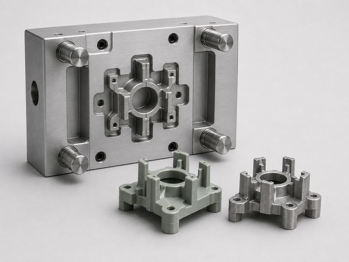
Micro MIM molds may require very precise core pins, inserts, gates, vents, and cavity details. Small errors in the mold can have a much larger effect on miniature parts than on larger components.
Tool wear also matters more at micro scale.
A small amount of wear on a large feature may be insignificant, but the same wear on a micro rib, small hole, or narrow slot may directly change the final dimension.
For high-volume production, tooling maintenance and dimensional monitoring should therefore be included in the production plan.
A good mold is not only required to produce the correct first sample. It also needs to maintain stable geometry throughout production.
Gate Design For Micro MIM Parts
Gate design has a major influence on miniature MIM components.
A poor gate location can cause incomplete filling, weld lines, flow marks, uneven packing, or distortion.
The gate should allow feedstock to reach the most difficult areas before the material loses flowability. At the same time, the gate should avoid critical cosmetic or functional areas where possible.
Gate removal is also more important on very small parts because the gate size can represent a large proportion of the component.
For this reason, gate design should consider both filling behavior and post-molding handling.
Venting Matters More Than It Looks
Venting is easy to overlook because it does not appear in the final component, but it is extremely important in micro MIM.
As the feedstock fills the cavity, the trapped air needs to escape. If venting is insufficient, air can block the material flow and create burn marks, short shots, incomplete features, or surface defects.
This is especially important around deep ribs, narrow slots, blind pockets, and end-of-flow areas.
Good vent design allows air to escape without allowing excessive feedstock leakage.
For micro MIM, venting should be considered as part of the mold design rather than only as a production adjustment.
Micro MIM Inspection Challenges
Producing a small feature is only part of the challenge. The feature also needs to be measured reliably.
Micro MIM components may require optical measurement systems, vision inspection, CMM, profile measurement, or special gauges depending on the geometry.
Very small internal features can be especially difficult to inspect.
Before specifying an extremely tight tolerance, the engineering team should confirm that the dimension can be measured consistently and repeatably.
A tolerance that cannot be inspected reliably creates unnecessary production risk.
Manufacturing capability and metrology capability should therefore be considered together.
When Is Micro MIM A Good Choice?
Micro MIM is especially suitable when the component combines small size, complex geometry, metal material requirements, multiple fine features, and meaningful production volume.
It becomes particularly attractive when several separate features can be integrated into one molded component. This can reduce part count, simplify assembly, and improve repeatability.
Typical applications include miniature medical mechanisms, precision instrument parts, small locking components, electronic hardware, micro gears, robotic mechanisms, and compact structural parts.
The economic advantage is stronger when the design takes advantage of the shape freedom of MIM rather than simply copying a part originally designed for another process.
When Should A Micro MIM Design Be Reviewed?
A design review is especially important when the component includes walls below approximately 0.5 mm, very small holes, deep blind holes, narrow slots, thin arms, fine threads, undercuts, or several critical micro dimensions.
These features are not automatically impossible.
They simply require closer evaluation because tooling strength, mold filling, shrinkage, warpage, and inspection become more sensitive.
Reviewing these points before tooling is usually far more efficient than modifying the mold after the first samples.
Micro MIM Design Checklist
Before opening tooling, engineers should review the following:
| Item | Review Question |
| Wall Thickness | Is the wall uniform and fillable? |
| Small Holes | Can the core pin remain stable? |
| Deep Holes | Is the aspect ratio practical? |
| Ribs | Are they too thin or too deep? |
| Slots | Can feedstock reach them reliably? |
| Corners | Can small radii be added? |
| Gate | Does the gate support balanced filling? |
| Venting | Can trapped air escape? |
| Shrinkage | Has dimensional compensation been considered? |
| Warpage | Can the part remain stable during sintering? |
| Tolerances | Which dimensions are truly critical? |
| Inspection | Can critical features be measured reliably? |
How XY-GLOBAL Supports Micro MIM Projects
Micro MIM projects require coordination between product design, tooling, feedstock selection, injection molding, debinding, sintering, inspection, and surface finishing.
XY-GLOBAL supports custom MIM components from design review and tooling through sample validation and mass production.
For miniature parts, the engineering review focuses on fine feature manufacturability, shrinkage compensation, tooling reliability, sintering deformation, dimensional inspection, and batch consistency.
For parts with thin walls, small holes, narrow slots, micro ribs, or tight assembly features, reviewing these points before tooling can reduce later modification and improve production stability.
FAQs for Micro Metal Injection Molding(MIM)
1. Can Micro MIM Produce Parts Below 1 Gram?
Yes. Very small metal components can be produced by micro MIM when the geometry, tooling, material, and handling process are suitable.
2. Can Micro MIM Produce Very Small Holes?
Yes, but the practical limit depends on hole depth, core pin strength, material flow, and tolerance requirements.
3. Is Micro MIM Suitable For Thin-Wall Components?
Yes. Thin walls are possible, but mold filling, debinding stability, and sintering deformation must be considered.
4. Can Micro MIM Produce Complex Internal Features?
In many cases, yes. Complex internal features may require special tooling, inserts, slides, or geometry adjustment depending on the design.
5. Is Micro MIM Suitable For Mass Production?
Yes. Micro MIM is particularly suitable for high-volume production of small, complex metal components where repeatability and feature integration are important.
Conclusion
The main challenge in micro MIM is not simply producing a small metal part. It controls many small features at the same time.
Wall thickness, hole size, tooling strength, feedstock flow, shrinkage, warpage, and inspection all become increasingly important as component size decreases.
For this reason, micro MIM design limits for small metal components should always be evaluated based on the complete geometry rather than one isolated dimension.
A very small feature may be practical when it is short, well supported, and located in a favorable flow path. The same feature may become difficult when it is deep, unsupported, or placed in an unfavorable area of the mold.
Early design review is therefore one of the most effective ways to improve tooling reliability, reduce modification, and achieve more stable micro MIM production.


Condividi:
Pressatura di polveri metalliche per componenti metallici ad alta precisione